GCS low-voltage withdrawable switchgear
use
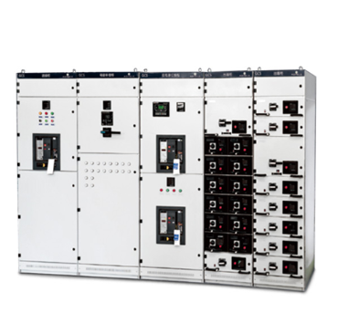
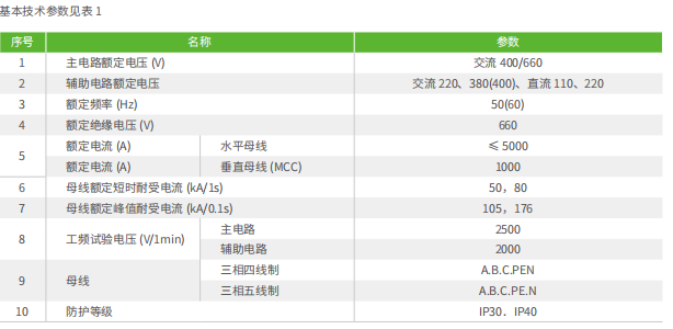
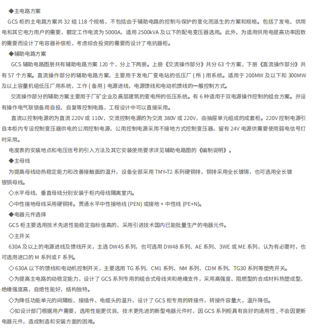
GCS type low-voltage withdrawable switch cabinet, suitable for power distribution systems in power plants, petroleum, chemical, metallurgy, textiles, high-rise buildings and other industries. In large power plants, petrochemical systems and other places with high degree of automation and computer interface, it is used as a low-voltage complete power distribution device for power distribution, centralized motor control and reactive power compensation in power supply systems with three-phase AC frequency of 50(60)Hz, rated working voltage of 400V,660V and rated current of 5000A and below.
device conforms to the following standards: Qiu C439-1 "low voltage switchgear and control equipment" GB7251 "low voltage switchgear".
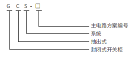
Model Meaning
normal conditions of use
& loz; The ambient air temperature shall not be higher than +40P, not lower than -5°C, and the average temperature shall not be higher than + 35C in 24 hours. If it exceeds the limit, it is necessary to reduce the capacity according to the actual situation;
& loz; For indoor use, the altitude of the place of use shall not exceed 2000m;
& loz; The relative humidity of the surrounding air shall not exceed 50% when the maximum temperature is + 40C, and a larger relative humidity is allowed when the temperature is lower, such as 90% when the temperature is + 2CTC. The influence of accidental condensation shall be taken into account due to temperature changes;
& loz; and the inclination of the whole set of cabinet rows relative to the vertical plane during installation of the leveling device shall not exceed 5 ° (in accordance with the GBJ232-82 standard);
& loz; The device shall be installed in a place free from severe vibration and impact and insufficient to cause electrical components to be undue corrosion;
& loz; When users have special requirements, they can negotiate with the manufacturer.


installation and application
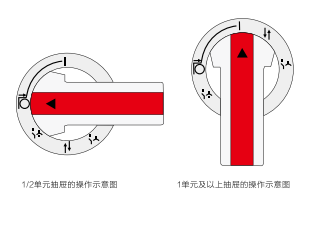
Working position: the main switch is closed, the main circuit and control circuit are connected, and the function unit is locked.
Opening position: the main switch is opened, the control circuit is connected, and the function unit is locked.
Test position: the main switch is opened, the main circuit is disconnected, the control circuit is connected, and the function unit is locked.
isolation position: drawer extraction 30mm. The main and control circuits are isolated and disconnected, and the drawer is locked.
Withdrawal position: both the main circuit and the control circuit are disconnected, and the drawer is arbitrarily withdrawn.
The operating handle can only be turned from the (O) position to the (|) position after being pressed 6mm in.
working process: the drawer can be pushed or pulled out only when the drawer is pulled out (N). After turning 45 counterclockwise, the drawer can automatically reach the isolation position when pulled out. Rotate the cochlea 45 ° to reach the test position (^). Turn 45 ° clockwise again to reach the switch breaking position (O). Press the handle down by 6mm and turn it 90 ° clockwise, then switch on the switch. If it needs to be withdrawn, operate in reverse order.
If necessary, padlocks can be added to the operating handle at the three positions of main switch opening, test and isolation as safety protection.
& loz; Unit & above drawer operation
The operating mechanism of the drawer is composed of a rotating shaft, a cylindrical cam, a clutch tooth plate, an axle pin compression spring, a shift fork, etc. The drawer can be inserted and dialed by rotating the cylindrical cam through the operating handle and has the functions of opening, closing, testing, isolating and locking the switch at the same time.
Working position: the main switch is closed, the main circuit and control circuit are connected, and the function unit is locked.
Opening position: the main switch is opened, the control circuit is connected, and the function unit is locked.
Test position: the main switch is opened, the main circuit is disconnected, the control circuit is connected, and the function unit is locked.
isolation position: drawer extraction 30mm. The main and control circuits are isolated and disconnected, and the drawer is locked.
Pull-out position: both the main circuit and the control circuit are disconnected, and the drawer can be pulled out at will. The operating handle can be turned from the (O) position to the (I) position only after it is pressed 9mm in.
working process: when the drawer is in the pull-out position (), the drawer can be screwed in or out. after the operating handle rotates clockwise by 30 degrees, it reaches the isolation position (m), and then rotates clockwise the operation diagram of the 1/2 unit drawer.
, after reaching the test position, continue to rotate 30 ° clockwise, reach the switch breaking position (O), press the handle 9mm in and rotate 90 ° clockwise, then close the main switch. If you need to exit, operate in reverse order.
If necessary, padlocks can be added to the operating handle at the three positions of main switch opening, test and isolation as safety protection.
♦ Unlocking mechanism
There is a red plastic button in the lower right corner of the drawer of unit 1 and above, which is the unlocking mechanism. When the operating mechanism fails, repairs or needs to be opened, press the red plastic button down to open the door when the operating handle is in the "." position.
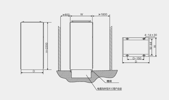
Outline and installation dimension

Factory data and accessories
The following documents and attachments shall be provided when the manufacturer supplies the goods.
& loz; Shipping List
O Product certificate and delivery test report
& loz; Instruction Manual
& loz; related electrical drawings
& loz; Main Components Instruction
& loz; Cabinet door keys, operating handles and spare parts specified in the contract.
Ordering Instructions
When ordering, the user shall provide:
& loz; Main circuit distribution system diagram and layout plan, rated working voltage, rated working current, setting current of protection device and necessary technical parameters.
& loz; Indicate the incoming and outgoing cable specifications.
& loz; model, specification and quantity of main electrical components in switchgear.
& loz; If busbar bridge or busbar duct is required between switch cabinets or incoming cabinets, specific requirement data such as span and height from the ground shall be indicated.
& loz; When the switch cabinet is used in special environmental conditions, it should be specified when ordering.
& loz; switch cabinet surface color and other specific requirements.


![[15]GCS 低压抽出式开关柜-低压开关柜系列-光伏并网柜_光伏箱变_固体绝缘环网柜_充气柜-众用电气 [15]GCS 低压抽出式开关柜-低压开关柜系列-光伏并网柜_光伏箱变_固体绝缘环网柜_充气柜-众用电气](http://nwzimg.wezhan.net/contents/sitefiles3607/18037698/images/7872658.png)
![[15]GCS 低压抽出式开关柜-低压开关柜系列-光伏并网柜_光伏箱变_固体绝缘环网柜_充气柜-众用电气 [15]GCS 低压抽出式开关柜-低压开关柜系列-光伏并网柜_光伏箱变_固体绝缘环网柜_充气柜-众用电气](http://nwzimg.wezhan.net/contents/sitefiles3607/18037698/images/7872658.png?x-oss-process=image/resize,m_lfit,h_200,w_200)


