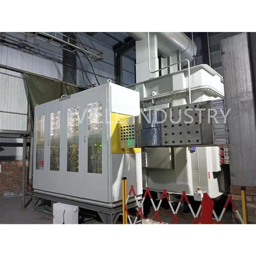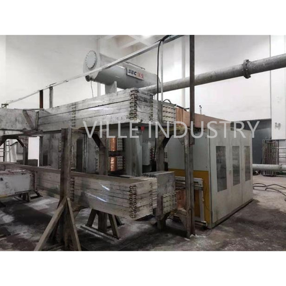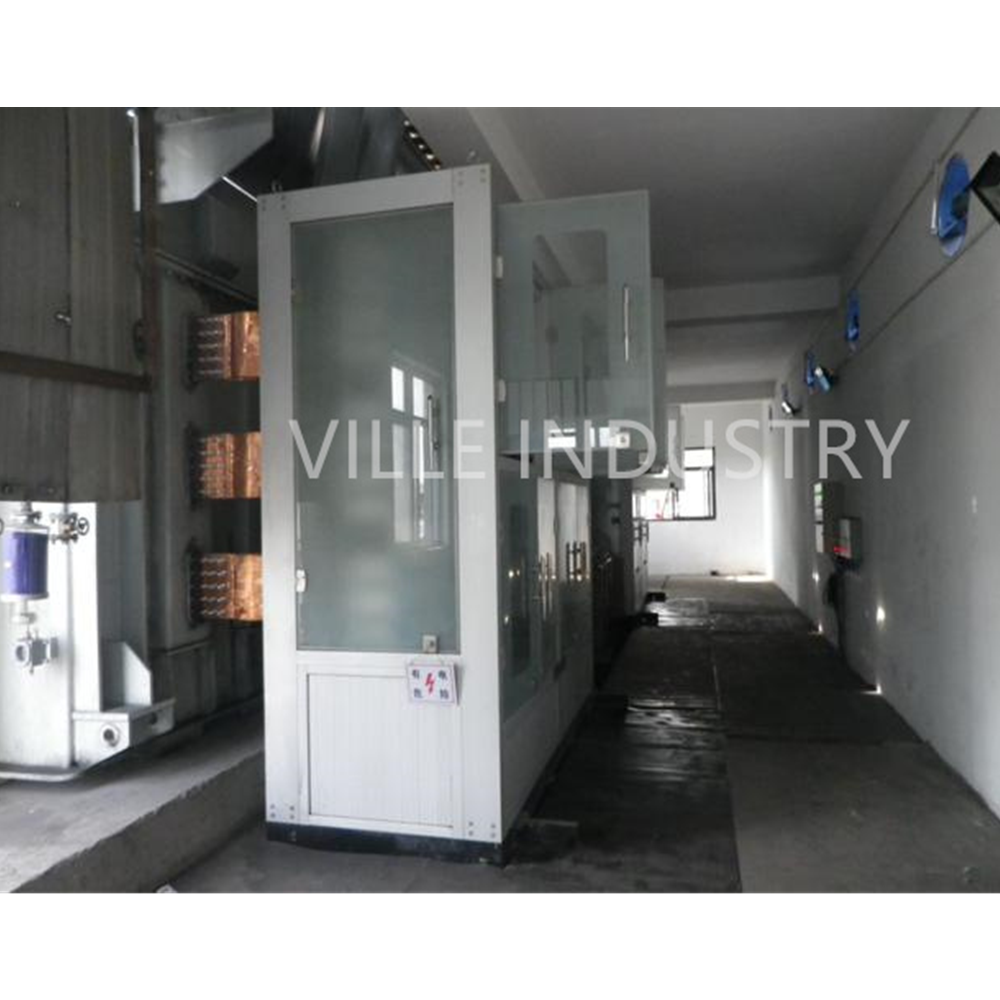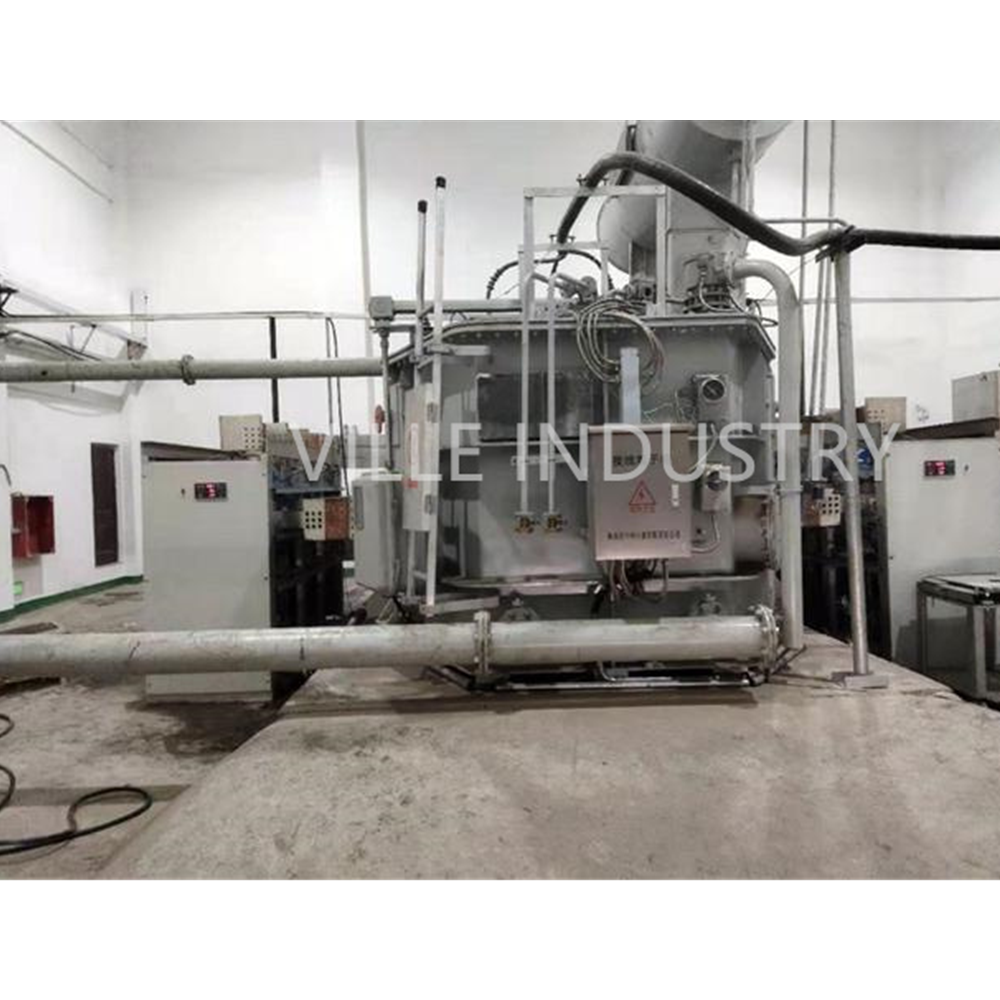


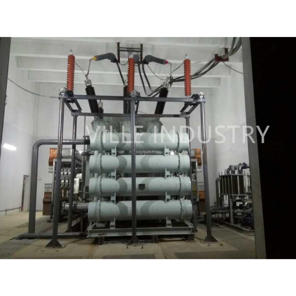
ZHS-2×60kA / 200V 12 phase rectifier
The application scope of this technical scheme is limited to 30000t / year new graphitized material engineering rectifier.Including technical specifications for functional design, structure, performance, installation and test of rectifier unit body and supporting equipment meeting the requirements of the project.
The standards and
2 (two) 120 kA / 40-200 V DC Rectiformers in single and parallel Operation New graphite material ZHS-2×60kA / 200V 12 phase rectifier
2 (two) 120 kA / 40-200 V DC Rectiformers in single and parallel Operation New graphite material ZHS-2×60kA / 200V 12 phase rectifier
1. Application scope and basis
The application scope of this technical scheme is limited to 30000t / year new graphitized material engineering rectifier.Including technical specifications for functional design, structure, performance, installation and test of rectifier unit body and supporting equipment meeting the requirements of the project.
The standards and technical requirements on which the technical scheme is based are based on national GB and international IEC standards and the latest in the industry
New standard JB and user technical specification for DC rectifier (1).
2. Basic design electrical conditions
2.1 rated condition of single unit rectifier:
DC voltage: udn = 40-200v
DC current: IDN = 2×60KA
2.2 overall configuration:
The single unit 120ka consists of one on load voltage regulating rectifier transformer with two diode rectifiers. Each diode rectifier outputs DC current of 60kA and DC voltage of 40-200v. Each diode rectifier is 6-phase rectifier. The two rectifiers are connected in parallel to form equivalent 12 pulse wave and output DC current of 2×60kA, DC voltage 40-200v
Or a single unit 120ka consists of an on load voltage regulating rectifier transformer with a diode rectifier, with an output DC current of 120ka and a DC voltage of 40-200v.
Single unit 12 pulse, two units in parallel to form a 24 pulse rectifier system.
2.3 the rectifier line adopts double inverse star with balance reactor, which is fixed inside.
2.4 electrical conditions for normal use
2.4.1 power supply voltage: 20kV ± 5%
2.4.2 frequency: 50Hz ± 0.5
2.4.3 number of phases: 3
2.4.4 power supply: AC380 / 220V ± 5%
2.4.5 control protection: AC220V ± 5% or dc220v
Frequency: 50Hz ± 0.4
|
Ser.No. |
Description |
Unit |
Design |
Seller |
|
|
|
|||||
|
Item 1 |
Auto-Regulation / Rectifier Transformer Combination |
|
|||
|
1 |
Supply voltage |
V |
20,000 |
20,000 |
|
|
2 |
Frequency |
Hz |
50 |
50 |
|
|
3 |
Maximum short-circuit power |
MVA |
866 |
866 |
|
|
|
Auto-Regulation Transformer: |
|
|||
|
4 |
Number of transformers |
pc. |
2 |
2 |
|
|
5 |
Throughput rating per unit |
MVA |
|
28 (+20%) |
|
|
6 |
Vector group |
- - |
|
D(+7.5°)/y11 ; D(-7.5°)/y11 |
|
|
7 |
Short circuit impedance |
% |
|
4- 6 |
|
|
8 |
Tap charger operation |
- - |
motor
operation |
motor
operation |
|
|
9 |
On-load tap charger positions |
- - |
70 positions |
71 Pos. (MR Tap-changer) |
|
|
10 |
OLTC tap step |
V DC |
2.3 |
2.33 (with saturable reactor ) |
|
|
11 |
Off circuit tapping switch |
- - |
3 positions |
N.A |
|
|
|
Rectifier Transformer: |
(with IPT and Saturated Reactor) |
|||
|
12 |
Primary voltage |
V |
adapted to output of step-down transformer |
adapted to output of step-down transformer |
|
|
13 |
Primary rating per unit at max secondary voltage |
MVA |
|
28 |
|
|
14 |
Secondary rating per unit at max secondary voltage |
MVA |
|
396 |
|
|
15 |
Maximum secondary voltage, at no load |
V |
|
330 V (A.C) 200 V(DC) |
|
|
16 |
Minimum secondary voltage, at no load |
V |
|
69.8 V (AC) 40 V(DC) |
|
|
17 |
Short circuit impedance |
% |
|
6-7 |
|
2、 Technical scheme of rectifier unit
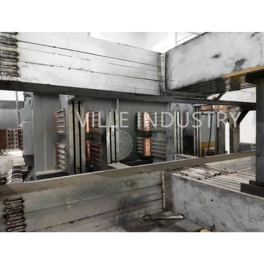
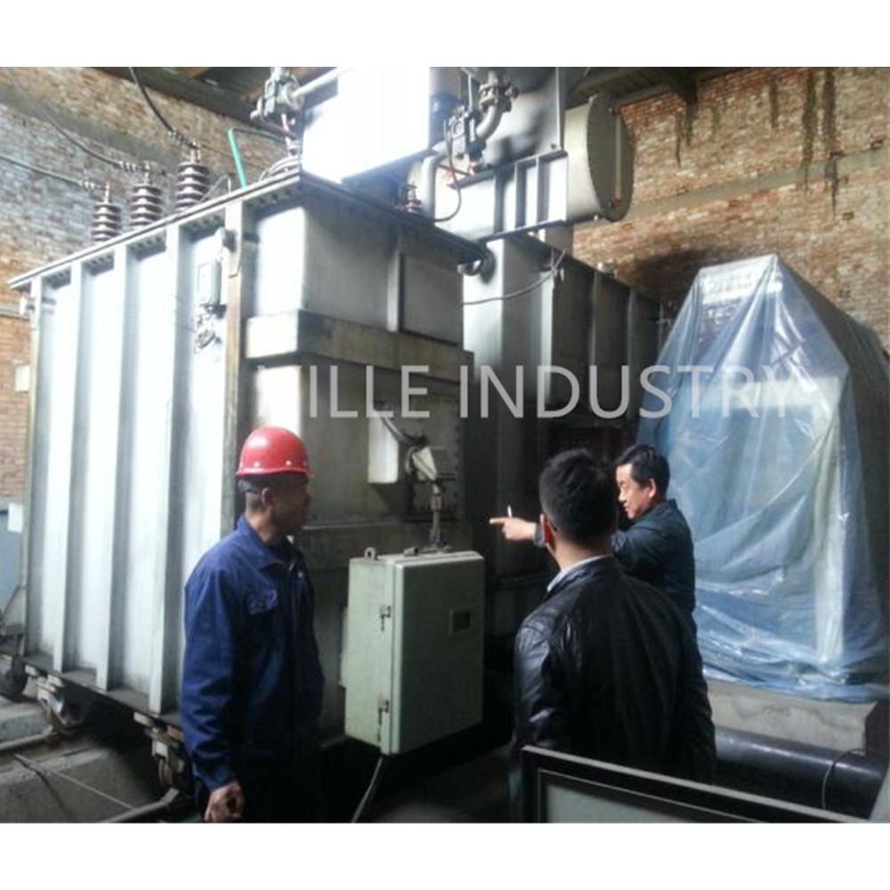
1. On load voltage regulating rectifier transformer
1.1 high voltage incoming line: 20kV
1.2 cooling mode: forced oil water cooling (ofwf)
1.3 voltage regulation mode: adjust the rectifier output current and DC output voltage through 70 level on load switch,
The voltage regulation range is dc40v-120v, which is continuously adjustable.
1.4 rectifier circuit: double reverse star rectifier circuit
1.5 impedance voltage: 8%
1.6 outlet mode at valve side: corresponding to rectifier cabinet without crossing.
1.7 see on load voltage regulating rectifier transformer for other details
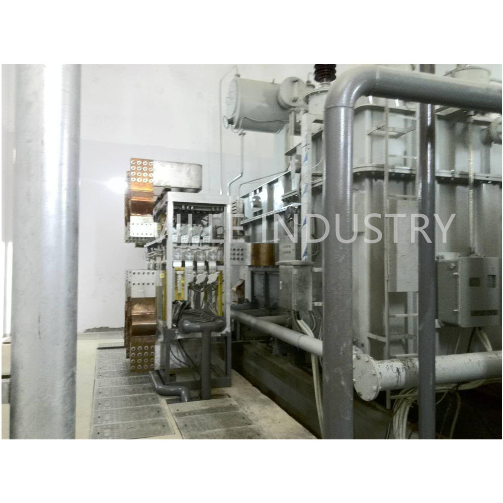
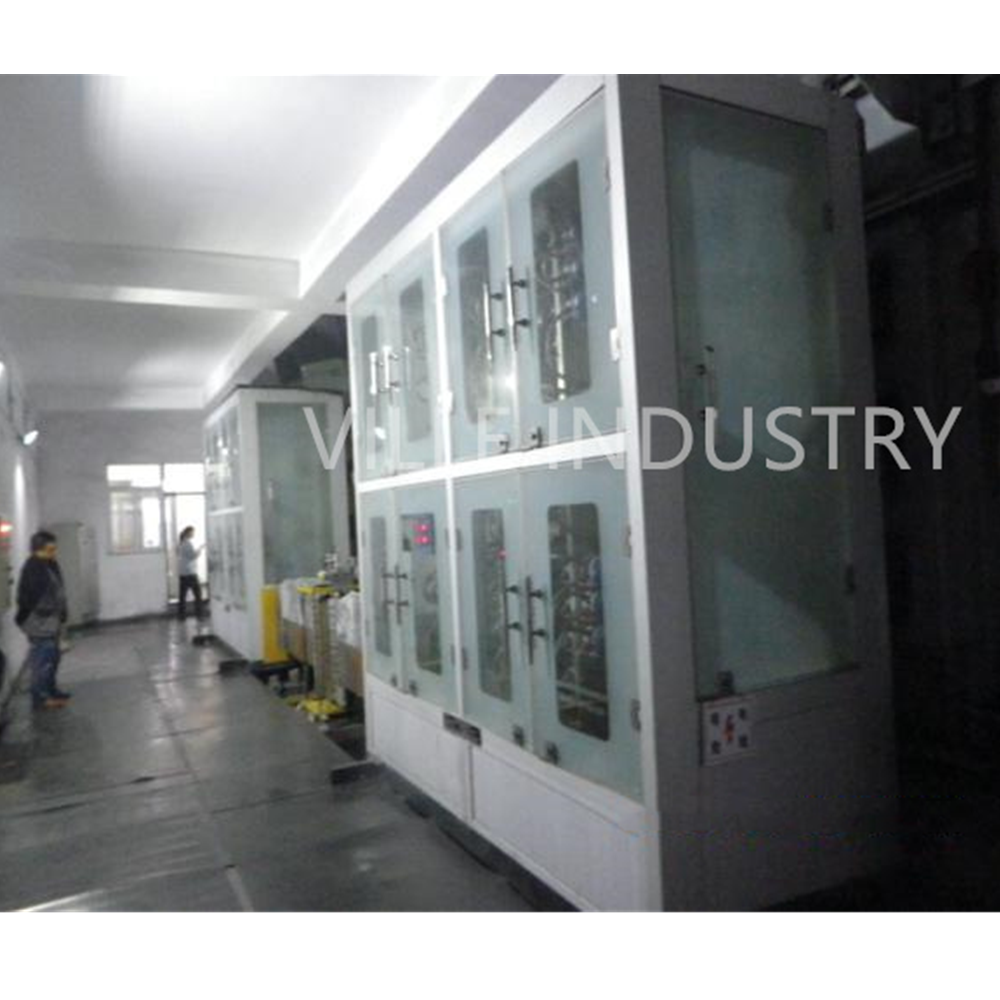
2. Rectifier cabinet (main circuit)
2.1 connection mode:
Double anti star rectifier circuit with balanced reactor is adopted.Single unit 12 pulse.
2.2 model: zhs-2×60KA/200V
2.3 rated DC current: 120000a.
2.4 rated DC voltage: UD = 40-200v.
2.5 rectifier element:
The high-power and low loss crimped zp6000a / 1800V diode element produced by Zhuzhou CRRC or Xi'an Perry is adopted. The forward average current is IAV = 6000a and the reverse repetitive peak voltage urrm = 1800V.
It adopts high-power components with low power consumption, strong overload capacity, high current sharing coefficient, high equipment operation reliability and high efficiency.
2.5.1 number of parallel elements per arm NP
nP=IA(AV)Kg KAI / (IT(AV) KCI KI Kf Kq Kv Kh )
In consideration of sufficient margin, take NP = 8 (PCs.)
2.5.2 the actual element current reserve coefficient Kr is:
Current of each arm 120000 / 12 = 10000 (a)
KR=8×6000 / 10000 = 4.8 (Times)
2.5.3 element voltage reserve coefficient KAV
Based on the actual reverse voltage uarm borne by the element,
UARM=1.414UVO
KAV2= URRM/ UARM=1800/1.414×one point seven three two×192 = 3.8 times